OSI Reference Model
Now that we are done with the basics of the devices we should get into the OSI reference model. The OSI model is a tool that can be used to help troubleshoot problems in your network. The OSI model is comprised of 7 layers, each layer focuses on different aspects of data transmission. This layered approach allows us to break down problems and take a step by step approach to resolving them. The seven layers of the OSI model, from the top down are
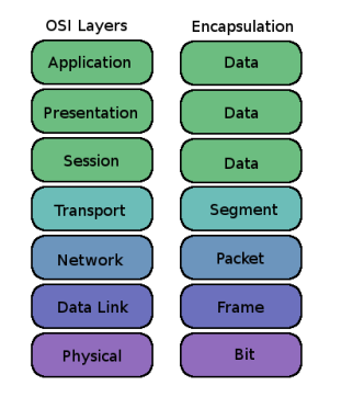
Application, presentation, session, transport, network, data link, and physical. Memorizing the seven layers of the OSI model is extremely important. The OSI reference model is an invaluable tool to network engineers as it provides a means for us to take a strategic approach to troubleshooting by working through the layers of the OSI model to solve problems.
Application Layer
We will start our discussion of the OSI model with the Application layer. The application layer is the link between the the program you are running and the behind the scenes networking. It allows the actual application to access networking services and send and receive data from the lower layers of the OSI model. There is a lot of stuff happening in the application layer but most of the information is not very useful to us for the CCNA.
Presentation Layer
The next layer is the presentation layer. The presentation layer translates data and code formatting to the application layer. Common tasks that are performed at this layer include compression and encryption.
Session Layer
The session layer is responsible for setting up, managing, and breaking down sessions between different presentation layer processes. This layer coordinates communication between different device systems. This layer is where simplex, half duplex, and full duplex are defined.
Transport Layer
The transport layer is the first major layer that is important to us studying for the CCNA. The transport layer is where the TCP and UDP protocols reside. TCP is considered connection oriented whereas UDP is connectionless. We will start with TCP which is more important to the CCNA exam.
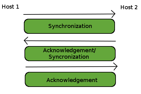
TCP is a connection oriented transport layer protocol. Connection oriented means that TCP establishes the connection via a three way handshake process. Lets say router 1 is trying to communicate to router 2, router 1 starts the communication process by sending out a SYN packet to router 2. Router 2 responds with a SYN/ACK packet; once router 1 receives this packet it sends a ACK back to router 2 and the connection has been established. TCP is also considered reliable because it requires the receiving machine to acknowledge data that it receives. This ensures that any data that is lost or corrupt will be re-sent. Corrupt and lost data can occur when certain events occur in your network. For example lets say that too much information was received on a rotuer and some of it was lost, the router would not acknowledge receipt of that data and the sending router would re-send it.
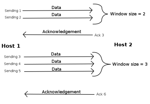
Data flow can be controlled through TCP by using something called window sizes. A window size is what defines how much data can be sent before an acknowledgement must be sent in return. With a window size of 1 the receiver would send an ACK for each segment received. With window size of 5 the receiving router would send an ACK for every 5 segments received.
Network Layer
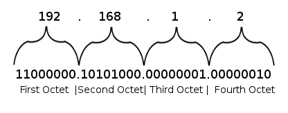
The next layer is layer 3, the network layer. This is where the IP protocol lives. IP addresses are 32 bit long addresses that define a device on a network. We will get into a more detailed discussion of IP addressing in a later discussion. The network layer is also where all internetwork traffic occurs. If traffic comes in from one network and must be routed to another network it all occurs on the network layer. There are 2 type of protocols that operate at the network layer, there's the rou TED protocols, and the rou TING protocols. The routed protocols are things like IP and IPv6, they are the things that get routed. Routing protocols are things like RIP, OSPF, and EIGRP, they are the protocols doing the routing. In other words the routing protocols are what determine where packets are sent around the network, this is called path determination, which if you remember is one of the routers functions I mentioned before. I also mentioned that the router is a layer 3 device which makes since that path determination is also present at layer 3.
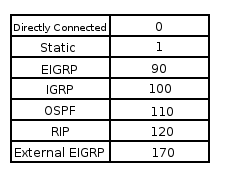
The network layer is also where the routing table is located. The routing table is a list of known connections to various networks. The routing table lists every route that the router has learned. The router can learn routes from different sources, such as static routes, or routes learned from routing protocols such as RIP, EIGRP, or OSPF. The routing table also contains information on the routes that it learned such as the metric to the route, the interface the router will send information on to get to that route, the IP of the next hop, the administrative distance, etc.. The metric is what the routing protocols will use to determine the best path for a route. The different routing protocols have different methods of calculating the metric and we will get into those when we discuss the protocols. The other piece of information I’d like to discuss is the administrative distance. Each type of route has an AD assigned to it. For example a route that was learned from RIP will have an administrative distance of 120, whereas a route learned from EIGRP will have an AD of 90. A directly connected neighbor will have an AD of 0, since the router knows that the destination is directly connected then there is no need to route through other routes. These AD values determine how much a router trusts that route. In the previous example a router learned about a RIP route and an EIGRP route. The RIP had a AD of 120 and the EIGRP had an AD of 90, based on these numbers the router will determine that it trusts the EIGRP route more because it has a lower AD. This is a very important concept to grasp. Each routing protocol has their own default AD-
Data Link Layer
The next layer is the data link layer which provides the physical data transmission, it specifies how to deliver data accross a particular link. The data link layer formats information into data frames which are sent out onto the physical link. These data frames are a part of encapsulation which we will discuss after the OSI model.
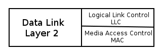
The data link layer is broken down into 2 sublayers, the MAC sublayer and the LLC sublayer. The MAC sublayer is where your MAC address resides. The MAC sublayer is also responsible for how packets are placed onto a link. The logical link control or LLC sublayer is responsible for identifying layer 3 protocols and encapsulating them, basically the LLC tells the data link layer what to do with a frame. Switches are present at the data link layer.
The data link layer is broken down into 2 sublayers, the MAC sublayer and the LLC sublayer. The MAC sublayer is where your MAC address resides. The MAC sublayer is also responsible for how packets are placed onto a link. The logical link control or LLC sublayer is responsible for identifying layer 3 protocols and encapsulating them, basically the LLC tells the data link layer what to do with a frame. Switches are present at the data link layer.
Physical
The physical layer defines all physical links, this includes all of your cabling. The physical layer is responsible for sending and receiving bits.
